Make Your Own Silver Audio Cables By Joseph Levy, The Vinyl Tourist |  |
| Don't have time for DIY? Please visit Tempo Electric, our commercial sister site, where we fabricate custom interconnects, speaker cables, and power cords for only a modest increase above the cost of materials. We also sell a full range of pure silver wire with Teflon® jacketing by the foot or by the meter for DIY projects. |
Update: 23 September 2010. It's been awhile since the last major revision, so I've rewritten this entire article in order to clear up the patch-work of updates, fix the broken links, and straighten out some bits of contradictory information. Included is my latest thinking about wire and gauges, as well as some new tips and more photos to make fabrication somewhat easier.
- Introduction
- Cable Types and Their Differences
- Interconnects
- Unbalanced or Single-Ended
- Balanced or XLR
- Coaxial or 75 Ohm
- I2S
- Loudspeaker Cables
- Interconnects
- Wire Gauge Selection
- The Debate
- The Trials
- The Conclusions
- Loudspeaker Cables: Recommended Gauges and Lengths
- Multiple Runs, Bi-Wiring, and Mixed Wire Gauges
- Materials and Sources
- Silver Wire
- Purity
- Temper
- Handling
- Jacketing
- Similar Size vs. Oversized Jacket
- Silver Wire
- Form Factor
- Symmetry
- Shielding
- Geometry
- Fabricating The Cables
- Wire Prep and Tools
- Assembling the Interconnects
- Assembling the Loudspeaker Cables
- Oxidation
Introduction
Are you an audiophile who's been frustrated by the high cost of loudspeaker cables and interconnects? If your introduction to hi-fi dates back to the 1960s and '70s, then you remember the days when "zip cord" (18 gauge lamp wire) was everyone's favorite speaker cable and colorful, spiral-wire interconnects, complete with molded plugs, were the norm. In fact, if they accounted for 1% of your system's cost, you were probably spending too much. It wasn't until Bob Fulton introduced "Fulton Brown" and "Fulton Gold" speaker cables in the late 1970s, that anyone give these a second thought.
Today, when the audio mantra is "Everything makes a difference," we typically budget 10% of our audio dollars for these ancillary items. It's hard to believe, but audio cables, often made from a variety of exotic materials, have been known to cost up to $40,000 per pair. Luckily, there's an antidote to this madness. While it will take a bit of time and patience on your part, there's a relatively short learning curve and the results are clearly worth the effort.
But first, a note from the lab. Although this page has been online in one form or another since 1997, it was only in the winter of 2005-2006 that I was able to put together a dedicated listening room with an audio system sensitive enough to allow listeners to distinguish the differences between even the slightest modification. With this long awaited tool at my disposal, I've continued to re-examine the subject, try some new ideas, and occasionally revisit some old ones.
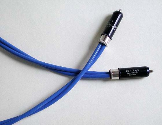
New Style "Big Twist" Interconnects with Oversized Jacket
Cable Types and Their Differences
Home audio conductors fall into two broad categories, interconnects and speaker cables. The former connect the source (turntable, CD player, tape deck, music server, tuner, and so on) to the control center (preamp, receiver, or integrated amplifier), as well as the preamp to the power amplifier. The latter connects the receiver or amplifier to the loudspeakers.
Interconnects
- Unbalanced or Single-Ended
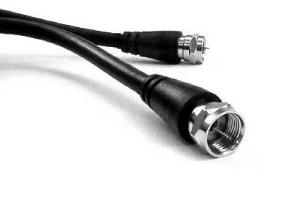
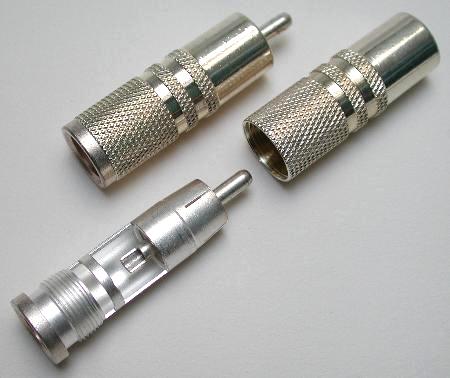
These are the most common interconnects found in home audio and are usually terminated at each end with an RCA plug, similar to the ones shown above or to the lower right. They have one positive (+) and one negative (-) conductor.
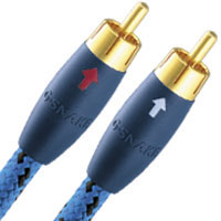 Sometimes there's a third "drain" wire, which is connected to the negative line at one end. The idea is that this wire, which is braided with or wrapped around the other two, acts as a shield and drains away any stray magnetism caused by the interaction of the principal conductors. However, its coverage is so skimpy, that it's always struck me as useless. If there is a drain wire present, there's often an arrow pointing to the connection end. Although most audiophiles point the arrow in the direction of the signal (starting from the source), it should really point toward the preamp or control center where the signal, itself, should be grounded. That way, the preamp acts as the center of a star ground at the point of the system's lowest potential, which is a more effective configuration.
In contrast, a true shield is a tubular copper braid which covers the entire length of the cable bundle and is attached to a separate wire. Ideally, this wire is connected to the earth ground either directly at the wall socket or somewhere in the audio system, usually via a component's metal chassis. However, if placed too close to the conductors, the shield can also truncate the high frequencies, dulling the overall sound. This can be mitigated by creating a small air space between the copper shield and the conductors. I've done this by wrapping the inner conductors with bubble-pak or inserting them in an oversized tube prior an applying the copper shield over that bundle. It's awkward, but it works.
As a practical matter, the shield is usually soldered to one end of the negative conductor, with an arrow pointing to that end. Never connect the shield to both ends of the negative conductor because this creates a ground loop, which has the potential to induce hum. You most often see the shield and separate ground connection wire on tonearm or turntable leads, because these cables are the most sensitive to outside interference, typically EMI (Electro-Mechanical Interference) or RFI (Radio Frequency Interference).
My original unbalanced interconnects with "similar size" jacket,
terminated with WBT-0110Ag NextGen locking RCA plugs.
For the majority of listeners, unshielded cables are fine for short distances of a meter or three. As long as the source impedance is low, the cables are properly dressed in relation to each other, and there are no nearby sources of RFI or EMI, there's very little chance of picking up noise and the signal will be fine. Unless you actually hear unwanted noise, don't loose sleep over shielding!
- Balanced or XLR
Balanced cables have three conductors, plus a shield for additional protection against noise. The conductors are Positive (In-Phase), Positive (Inverted-Phase), and a shared Negative. The shield should be a copper braid that covers the entire length of the cable and is connected to the earth ground through the XLR's metal barrel.
In a true balanced audio circuit, the two out-of-phase positive signals are recombined into one at the output. Any noise that was picked up along the way will be seen to have the same polarity on each wire and is therefore not seen by the receiving component. Only signals that are out of phase (of opposite polarity) are picked up. The noise on both wires is called common-mode noise and a properly balanced circuit will amplify the desired signal, while rejecting the common-mode noise.
Balanced cables are terminated with a 3-pin XLR connector, typically male at one end and female at the other, which also features a latch to keep them secured to the equipment. The metal shell or body of the XLR, itself, is typically used to connect the shield. This configuration differs slightly for professional audio applications, where balanced cables are widely used in recording studios.
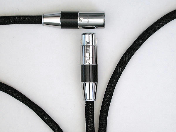
Balanced Home Audio Cables
The argument in favor of balanced lines is that they are immune to EMI and RFI, especially in long runs (typically over 12 feet or 3 meters). That's why they're the standard for professional audio, where they're used to connect a microphone to an amplifier or sound board and so on. The advantage for home audio exists mainly if the components they join together are designed with balanced circuits in the first place. If not (and most are not), there's no real point in using them. You'd only have to buy RCA-to-XLR adapters to interface the balanced cables with the unbalanced circuit. The only possible reason to use them in an unbalanced circuit is the presence of the independently grounded shield.
If you happen to have a component that has unbalanced circuitry, but is terminated with a chassis-mount XLR, you can avoid the use of an adapter by simply soldering the unbalanced positive (+) conductor to Pin 2 and the negative (-) to Pin 3. Leave Pin 1 unattached. In this configuration, the shield is optional and the (+) and (-) conductors can be connected to an RCA plug at the other end.
- Coaxial or 75 Ohm
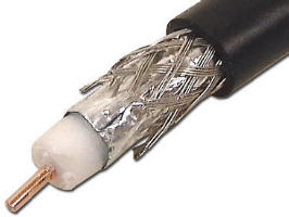
These are sometimes used in digital audio, as well as many video applications. Coaxial cables consist of a single positive wire, embedded in insulation (typically foam) that's surrounded by a copper braid which covers the entire length. The braid serves as both a negative conductor and a shield. The ones most commonly seen are used for video signals and require a special threaded connector, called a BNC, whose outer ring is crimped to the grounding shield, allowing the positive wire to protrude through the center. It's the type of wire that your carries your cable company's signal in from the street.
In 1929, coaxial cable was developed to meet the original specification for audio cables and, though rarely done today, can also be terminated with conventional RCA plugs. High-end DIY coaxial for home audio is beyond the scope of this article, though it may be added in the future.
- I2S
Pronounced "Eye-squared-S," this is a special 5-conductor cable that's found in a few digital audio components. It's main use in home audio is to connect separate CD transports to DACs and requires a 5-pin DIN connector. Because of the miniature solder pins inside, it's also more challenging for the DIYer to fabricate.
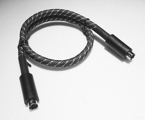
A commercial I2S cable
Commercially made loudspeaker cables usually have a spade, banana plug or, in less expensive designs, a heavy pin at one or both ends. However, they can also be fabricated in the balanced configuration and terminated with XLRs.
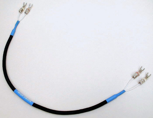
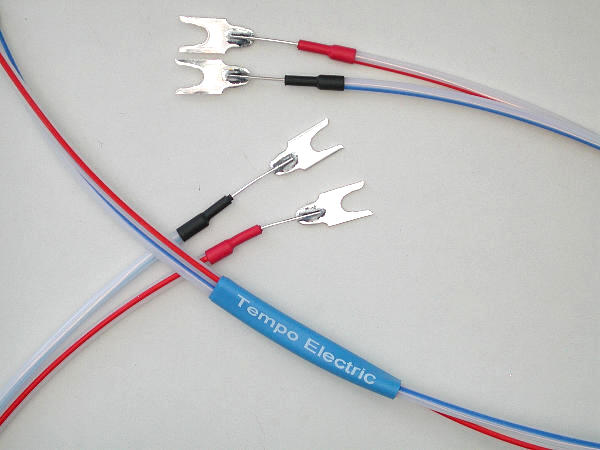
Loudspeaker cables terminated with WBT-0680 silver spades
and a decorative PVC/Nylon mesh jacket
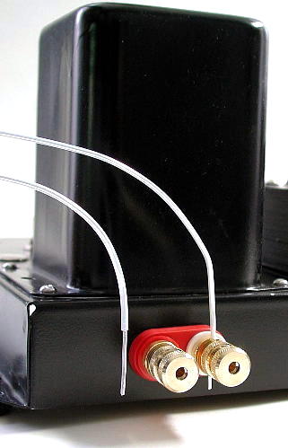
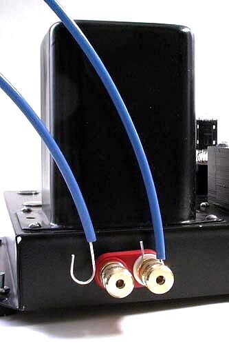
Unlike interconnects, which always need connecting hardware at each end, speaker cables don't actually require termination and can just be inserted into the center hole of a 5-way binding post. Alternatively, the ends can be formed into a loop and hooked around the posts which are then tightened. They can also be pushed into those cheesy spring-loaded clamps that grab the wire on cheaper electronics and speakers. Beyond that, the major difference will be the size or gauge of the wire.
Multiple Runs, Bi-Wiring, and Mixed Wire Gauges
At one time, it was popular to double the run of your wire in both directions (the "shot gun" configuration). My own tests suggest that you're better off just using a heavier gauge of wire to begin with (consult the chart below). However, if your speakers are equipped with dedicated binding posts for each driver, you may reap some benefit by bi-wiring. This means using separate cables for each driver, with a common termination at the amplifier end. The theory is that separate grounds for each driver create a more efficient signal path and my own experience bears this out.
There's also a hypothesis that various audio frequencies are reproduced best over different gauge wires and that a bundle of different gauges is better than a single conductor. Again, my experiments suggest that using a single conductor of the appropriate gauge throughout the system is all you really need. Multiple gauge bundles never sounded better to my ears and are just plain awkward to fabricate.
Wire Gauge Selection
The Debate
There is some debate about which gauge of wire is optimal for which application and, accordingly, where it should be used. The late Harvey "Gizmo" Rosenberg used 18 AWG (American Wire Gauge) speaker cables in his personal system at The Triode Guild and mentioned that Dan D'Agostino of Krell preferred the heavier 16 gauge wire. (See Gizmo's article in Positive Feedback for more on this subject.)
Allen Wright, author of The SuperCables CookBook, is a vocal advocate of using the thinnest wire possible, such as 30 AWG (or smaller) for interconnects and a thin ribbon of silver foil, 25 mm wide x 0.05 mm thick, for speaker cables. Do the math and you'll find that the latter actually translates into a cross section equivalent to 16 gauge, as well, albeit with a much larger surface area than round wire has.
On the other hand, Martin DeWulf, editor of the Bound For Sound Report, published an article in January, 2004, which extolled the virtues of 6 AWG copper speaker wire made from a cable type commonly found in the electrical departments of "Big Box" home improvement stores. In the 1980s, the late Enid Lumley, then a columnist for The Absolute Sound magazine, also shared this view (she called them "welder's cables"). Naturally, there were cases to be made on both sides. Gizmo's final experiments suggest that thinner is better and you can read the whole story in his article entitled "Less Is More."
The Trials
In the interest of science, I tried the BFS "Big Box" 6 AWG copper cables for myself and found them to be surprisingly good, especially since the price was only 30¢ per foot (now that's a bargain!). While 6 gauge silver wire should do copper one better, keep in mind that DeWulf and Lumley were referring to multi-stranded copper conductors that add up to 6 gauge. Solid silver in 6 gauge is about 3/16" (4mm) in diameter and is more like a rod than a wire, but conceptually, it occurred to me that one could try bundling smaller gauge silver wires to approximate 6 AWG. Curious to see if this idea had any merit, I used what was on hand and attempted to make a set of 8 gauge silver cables using multiples of both 13 and 16 AWG, but found that the mechanics were not as easy as they seemed. This configuration was frankly messy and difficult to manage. In the end, I concluded that it was best to stay with a single strand of wire, regardless of its gauge.
By comparison, in my own system, extra soft temper [a discussion of temper or hardness follows, below], 16 gauge solid silver wire out-performed all of the heavier copper gauges, including the 6 gauge home improvement store wire. It also bested the very expensive Kimber 8AG, a multi-conductor silver cable, equivalent to 9 gauge and fabricated from eight medium temper wires braided together. The DIY silver cables were clearly smoother, more open, and allowed more detail to emerge from the recording.
Whether it's copper or silver, if you do take the 6 gauge route, don't bother with spades or other connectors. One of the five ways a five-way binding post works is the hole in the center. Just insert the bare bundle and tighten. Since the conductive properties of silver are substantially higher than those of copper, an 8 AWG silver conductor will closely approximate the transmission properties of 6 AWG copper. However, given the cost and malleability of solid silver wire, 10AWG may be as large a gauge as one really needs to use.
In December, 2009, I continued the trials by comparing 30 gauge wire with 24 as a phono to preamp interconnect and preferred the 30 gauge. Though the difference was subtle, it seemed to open up the sound stage a bit more, as well as lift a very faint veil, bringing me closer to the performers. By comparison, with a digital front-end, the 24 gauge seemed to have the edge over 30 in bass performance.
In the summer of 2010, I fabricated a pair of 1 meter, hybrid interconnects for a client in Europe in which the positive (+) conductor was made from extra soft 24K gold wire and the return (-) conductor from extra soft silver. Since I knew that gold was not as good a conductor as silver (it's measurably true) and had heard that it tended to make the music sound a bit slower, I wasn't expecting much from this expensive experiment. However, I was truly surprised to hear noticeably less grain through the gold-silver hybrid pair. The sound was clearly more fluid and analog sounding, in a way that only live music can be. Although they seemed to shift the spectrum down a notch, the highs did not really suffer—in fact, they sounded even smoother—nor did the speed of the music. The benefits, at least on LPs, were all positive. Results varied from record to record and your equipment may tell a different story, but now I use them as my personal vinyl reference.
The Conclusions
In my personal system, the verdict regarding which gauge to use was out for a long time. Based on all trials to date (September, 2010), I now recommend 30 gauge for phono interconnects, 24 gauge for digital interconnects, and 16 gauge (or heavier) for speaker cables. In fact, further experiments suggest that you really can't go too heavy with speaker cables (shades of DeWulf and Lumley). In my own system, I currently use:
- 1 meter long, 30 AWG gold + silver hybrid interconnects from turntable (tonearm) to preamp
- 1 meter long, 24 AWG silver interconnects from digital sources (CD player, music server) to preamp
- 8-foot long, 24 AWG silver interconnects from preamp to 20 watt mono amplifiers
- 30-inch long, 12 AWG silver cables from amps to 91dB efficient loudspeakers
As an aid, I've put together this chart to help guide you in fabricating speaker cables:
| Recommended Minimum Wire Sizes for Loudspeaker Cables | ||
| Amplifier Output (Per Channel): |
If the total length is 8 Feet (2.4 Meters) or less: |
If the total length is greater than 8 Feet (2.4 Meters): |
|---|---|---|
| 1 - 19 Watts | 16 Gauge (1.3mm2) Wire | 16 Gauge (1.3mm2) Wire |
| 20 - 100 Watts | 16 Gauge (1.3mm2) Wire | 12 Gauge (3.3mm2) Wire |
| 101 - 200 Watts | 12 Gauge (3.3mm2) Wire | 10 Gauge (5.2mm2) Wire |
| Over 200 Watts | 10 Gauge (5.2mm2) Wire | 10 Gauge (5.2mm2) Wire |
Postscript
So, what if you're already using 20 or 24 gauge interconnects or speaker cables, as I once recommended? Should you ditch them in favor of 30, 24, or 16 gauge, as mentioned above? It really depends upon your level of obsession, your budget, and your sensitivity to subtle improvements in the audio path. For entry-level and mid-fi systems, it may be difficult to hear any difference. Only if you have the most refined set-up is it worth considering a change. Of course, if you're just starting down the silver path, why not standardize on 30 or 24 AWG for interconnects and 16 AWG (or heavier) for speaker cables to begin with?
Materials and Sources
"Fine silver round wire" can be purchased from jewelers, silver crafters, and other sources, including our sister site Tempo Electric. Purity should be at least .999 ("three nines"), but keep in mind that much of the gold and silver you may purchase has been refined from existing stock and is not necessarily "virgin" or newly mined. Poor refining of ore or recycled metal can leave a larger proportion of impurities, so buy from a reputable source.
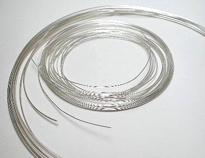
Coils of fine round silver wire
Regardless of form, sales of precious metals, including silver, are based on weight multiplied by today's spot market price, plus a percentage to cover the refiner's overhead and profit. On a given day, this can be as much as half-again or even double the spot price. For example, if today's price of silver is USD $20 an ounce, a refinery may it sell in wire form for $30 an ounce or higher. In turn, the retailer will mark it up again to cover overhand and generate some income. Remember, the price of silver changes from day to day depending on the world market, so it pays to check the spot market for trends. Generally speaking, the price for precious metals tends to be lower from January to July. Interestingly, part of the demand occurs because the Indian wedding season occurs in the fourth quarter of the year and gold and silver coins are a popular gift at wedding ceremonies.
Purity
Commercial or bullion grade silver is typically 99.9% to 99.99% pure, expressed in the industry as .999/.9999 or 3-nines/4-nines pure. The balance (0.1% or .01%) consists of various other trace metals that naturally exist in silver ore, are blended in with recovered silver, or are too expensive to refine out. To get 99.999% ("five nines") purity, you'll pay a hefty premium—as much as 500% over the cost of 3-nines. However, be wary of silver advertized as 5-nines or higher. It really doesn't exist in the commercial market place and if it did, the cost would be so high that you wouldn't be thinking of DIY cables in the first place.
Commercial audio cable makers have made a fetish about metals' purity that just doesn't make sense in the real world. Follow the signal path in your audio system. The leads on resistors, the foil used to form capacitors, the traces on circuit boards, and the formulation of solder all add up to a potpourri of metals—gold, nickel, copper, aluminum, tin, zinc, chromium, rhodium, even lead. Look beyond the hype and audio paranoia. In my experience, spending more on a level of purity that's higher than .999 or .9999 is a waste of money and the stuff that advertising is made of.
Temper
"Temper" refers to the degree of hardness of the metal and is determined by the amount of heating and reheating (annealing) used in the refining and finishing process. For years, I only purchased "regular" temper silver wire. However, with the completion of the new listening room, I was now in a position to do some serious investigation into the subject. In March, 2006, I ordered some "extra soft" temper wire from the refiner to try as loudspeaker cables. The difference between regular and extra soft was not at all subtle and the improvement was obvious from the very first note. Suddenly, the sound stage doubled in size, transparency increased by a similar magnitude, and details that were previously hidden, emerged from the darkness. When you make your purchase, be sure to specify "extra soft temper, fine silver, round wire." Given a choice, the importance of extra soft temper trumps a higher degree of purity every time.
Handling
When it arrives, the silver wire is bare. Avoid handling it with your fingers—over time, the acidic oils on your skin can degrade the metal's surface. Ideally, you should wear a pair of nylon, polyester, or cotton gloves, such as lint-free film handlers' gloves available from a professional photo supply store. An alternative are the thin plastic gloves that people in the medical and food industries favor, typically found at your local pharmacy. Industrial supplier McMaster-Carr sells Nylon tricot "inspection gloves" (their catalogue #5443T22), as well as those made from cotton (catalogue #5452T2).
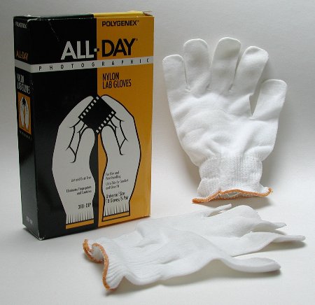
Nylon film handler's gloves
Jacketing
As if life weren't exciting enough, the type of jacket or insulating material used on audio cables has become a hot topic in the DIY forums, too. While PVC is a relatively inexpensive plastic, it only has moderate dielectric (insulating) properties—pass it up in favor of Teflon. From an electrical point of view, Teflon or it's generic types such as FEP or PTFE, are far superior.
Alternatively, it's become trendy to install audio wire in cotton tubing or even silk. The reason behind this is simple—cotton has a very low Dielectric Constant, while Teflon's is relatively high. What does this mean? Simply put, the Dielectric Constant is a number which is used to compare the relative insulating value of different materials. Air has a Dielectric Constant of 1.0, cotton's is about 1.3, and PTFE Teflon tubing is 2.0. Therefore, the insulating characteristics of cotton are closer to plain air, than those of Teflon. This also means that cotton's insulating characteristic isn't very good, which is why it's no longer used on electric wiring.
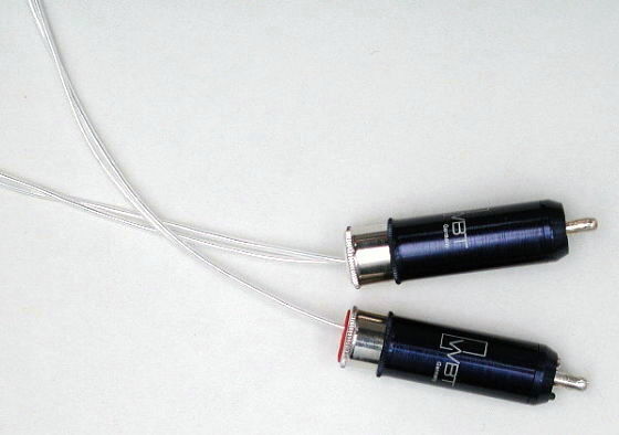
How does this relate to the sound of an audio signal? Curious to find out, I fabricated a pair of interconnects from 30 gauge silver wire that were completely bare—they had no insulation of any kind. Of course, I could not twist the conductors as I normally would, but with care, I was able to install the cables from my reference turntable to my preamplifier without shorting out the signal. Interestingly, I found that when compared to a pair of interconnects made in the usual way (30 gauge silver wire in a 28 gauge Teflon jacket), the uninsulated pair sounded much more open and the system projected a much larger sound stage. Clearly, the closer one could get to plain air, the better the sound. Hence, the vogue for cotton.
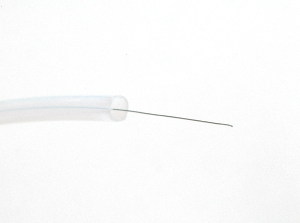
30 gauge silver interconnect wire in an 8 gauge (3.3mm) semi-clear Teflon jacket
However, cotton's low Dielectric Constant means that it offers little protection against outside interference. In fact, our uninsulated interconnects picked-up noise from the turntable motor, which we had never heard before. Often counteracted by twisting the wires, this is awkward to do with cotton and almost impossible to do with no insulation at all. We then tried a pair of interconnects made with 30 gauge silver wire and 8 gauge Teflon tubing. It turned out that the oversized Teflon jacket mimicked the perceived advantage of cotton piping (more air and a larger sound stage), while retaining the insulating properties of same-size Teflon. While the effect was more noticeable with interconnects and somewhat less with loudspeaker cables, based on these experiments I now recommend fabrication of all of your cables with oversized, flexible Teflon tubing.
Naturally, there are some situations where an 8 gauge jacket just isn't practical. For example, because of the limited opening on the ends of the connectors, 11 gauge is a better choice for 3-wire XLR connectors and 14 gauge is preferred for 5-pin DIN phono connectors. The exact gauge is less critical than getting as much air around the conductor, as practical.
Merits aside, never use cotton or silk insulation over wires in high voltage applications. You can use it wherever you can over signal wire, but never in any part of the circuit where high voltage is present. A hole in the cotton or a voltage spike jumping across the hot and neutral lines, can burn through the insulation causing a short circuit, damaging your component, or even igniting a fire.
Similar Size vs. Oversized Jacket
For years, I recommended same size Teflon jacketing for all cables. That means if you were using 24 gauge wire, you would thread it into 24 gauge (inside diameter) Teflon jacketing. This made prep work, like squared-off, burr-free wire cuts, as well as polishing, more critical to the final operation. However, now you have a much easier time of it. What I now refer to as similar size tubing is close in size, but 2 to 4 gauges larger, than the wire itself. For example, 24 gauge wire can go into 20 gauge tubing, which is a lot easier to do and haas the benefit of more air around the conductor, à la cotton. But what about oversized tubing? Of course, with even more air around the wire, that's the best solution of all. However, it comes at a price. Similar size Teflon spaghetti tubing in 16 to 28 gauge is relatively inexpensive. Oversized tubing, like 8 gauge, costs 10 to 20 times as much. In some cases, where talking about a relative price difference of 10¢ vs. $2 or more per foot. Depending upon your situation, this can add up to real money. Similar size wire is also easier to maneuver. Plastic tubing, especially in larger sizes, has a sort of memory and won't always lay flat or curve the way you want it to. Put a very small wire inside a very large, flexible tube and it's the tube that tells the wire which way to bend. Put a wire inside a similar size tube and the wire controls the geometry. A delicate 30 gauge wire inside a relatively massive 8 gauge tube can easily break off at it's solder connection if the whole bundle isn't properly secured.
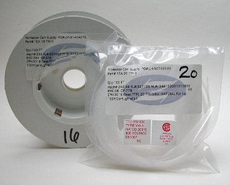
Coils of similar size Teflon tubing
PTFE Spaghetti Tubing, Standard Wall Thickness, (which is the technical name of the Teflon insulating jacket) can be purchased from McMaster-Carr. A 100-foot (33 meter) roll of 16 AWG tubing costs about $18.00, 20 AWG tubing costs $14.00 for 100 feet, and 24 AWG costs $8.00 for 100 feet. The catalog numbers for 16, 20, and 24 AWG tubing are 5335K16, 5335K13, 5335K12, respectively. To locate it in their online data base, do a keyword search using those numbers. There will be a link to the full page where you can find other gauges, as well. Some DIYers prefer thin-wall PTFE tubing, which can be sourced from Small Parts, Inc.. Prices are somewhat higher, however.
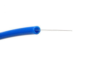
30 gauge silver interconnect wire in an 8 gauge (3.3mm) solid color Teflon jacket
McMaster, as well as Small Parts, also sells oversized Teflon tubing in natural (semi-clear), as well as solid and striped colors. Be advised that the oversized semi-clear and striped tubing is somewhat stiffer than the solid color tubing. The latter has a smaller turning radius and is a better choice for interconnects which often have to squeeze into spaces with minimal clearance behind equipment racks. Semi-clear or striped tubing is fine for speaker cables however. When building speaker cables, to hold the wires in place, I install short pieces of color-coded, adhesive-lined, 02B2 heatshrink tubing, available from heatshrink.com, a division of Kimber Kable. 1/4" (6.4mm) heatshrink is the right size for 8 gauge tubing. For a better fit, I often slip a smaller piece of 1/8" (3.2mm) heatshrink over the wire, too, but inside the 1/4" heatshrink. More detailed information follows, below, in the assembly section.
Form Factor
Symmetry
Regardless of their form or gauge, it's important to keep both left and right cables equal in length, even if your electronics are closer to one speaker than the other. This keeps the audio circuit symmetrical and prevents the possibility of phase shift—the arrival of the signal at each speaker (as well as your ears) at different times.
Shielding
As I touched upon in the Cable Types section, above, audio cables not only conduct the audio signal, but in extreme situations can also act as an antenna picking up RFI, mainly in the form of radio broadcasts, and EMI, usually a hum or buzz that's caused by a nearby electrical field. These phenomena are completely local and somewhat unpredictable.
By way of example, for almost 15 years, I lived in a very rural part of New York State where the neighboring properties were principally dairy farms, spaced miles apart from each other. Yet, every evening, if I put my ear close to the loudspeakers, I could distinctly hear a far-off radio station. And every night from 8 PM through 1 AM, for two of those years, there was a distinct buzz, probably caused by a poorly grounded mercury vapor lamp hanging from a barn up the road, a couple of miles away. The buzz was apparently travelling down the single power line that serviced every house on the road. Today, my listening room is in an office building (unusual, but true) located in the heart of a mid-sized city. There's a college radio station within sight, sitting on a hill five blocks away, a taxi stand across the street that communicates with its fleet via short-wave, and who knows what else. Yet, despite all this, I've never heard anything at this location coming from my stereo, other than music. I mention this, because it's the urban environment, not the rural, that's notorious for RFI, so these problems are often inconsistent.
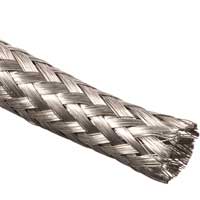 Technically speaking, the only way to completely make one's audio cables immune from RFI and EMI is total shielding with tubular tinned copper braid (shown right) and a shield-to-earth connection. This is the way balanced or XLR cables are constructed. Unfortunately, I've found that this type of direct shielding also tends to restrict the higher frequencies (>10KHz) which, in turn, reduces air and transparency. However, I'm experimenting with configuring a shield that avoids this problem and will publish my findings as they progress. Based on personal experience, most audio systems (like my current one) don't require shielded cables, but be aware that in some locations it may be a necessity.
Geometry
For a dozen years, I experimented with different schemes that either completely separated the (+) and (-) conductors or twisted them tightly together. Under ideal circumstances, hot and neutral wires that are completely separated work perfectly well. You can arrange them an inch or more apart and impress your friends by calling it an "air dielectric." Nelson Pass, well-known amplifier designer and frequent contributor to Audio Xpress magazine, suggests that 6 inches is the ideal, but my experience suggested that the exact distance wasn't critical—generally, each conductor could dangle freely without ill-effect.
However, the problem with the "free air" arrangement is that it's not very practical. Even in a relatively simple system, all of the cables dangling or crossing one another can easily become one giant mess. In addition, there are those who feel that loose wires, even those run in parallel, are still antennas and an invitation to RFI, especially when used as interconnects to pass low level signals. They advocate braiding or twisting the conductors, with or without some sort of shield or drain.
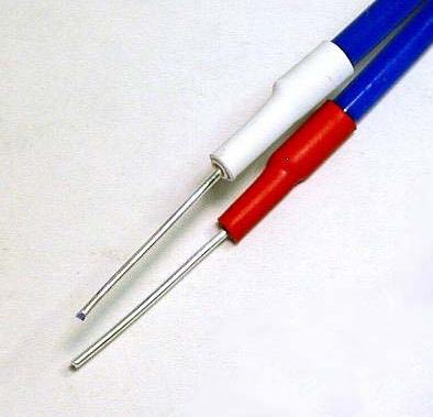
The major issue with a tightly twisted pair of wires is that you run the risk of stressing their skin, where some listeners theorize that the high frequencies travel. After years of trial and error, I've found that simply adding a gentle twist to the conductors at a rate of 3 or 4 twists per foot, works well for both interconnects and speaker cables. see the first photo in this article, at the top of this page, for an example. Through it adds a bit of capacitance when compared to parallel conductors in free air, it's a simple cure for the lowest level EMI and simplifies cable dressing or arrangement.
Fabricating The Cables
Enough theory—let's make some cables!
Wire Prep and Tools
To begin, simply cut your coil of silver wire to the desired lengths. Careful with the 30 gauge—it's very delicate! I like to use a long worktable that allow me to set up a 6-foot ruler. As a test for proper length, you may want to use some cheap copper wire first in order to verify the correct run between your components. It's important to allow enough length to avoid sharp turns or bends, which stresses the outer skin of the wire.
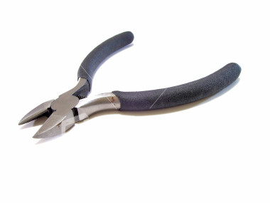 When you cut the wire, use the type of clippers (shown right) that are designed for electronics. Hold them so the blades are at right angles to the wire strand. That way, the surface of the cut end will be perpendicular to the length of the wire, itself. This minimizes burrs, which can make it difficult to thread the conductor into the jacket.
Though more critical with smaller gauge tubing, inserting the wire into the jacket is much easier if you polish it with steel wool, first. Many DIYers, as well as manufacturers, say that the smoother surface of polished wires make them sound better, but this is a level of minutiæ that I have not been able to verify. On the other hand, it only takes a few minutes, doesn't add to the cost, and by straightening out any kinks or turns, makes the operation much easier.
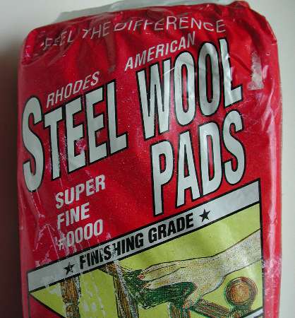
While Allen Wright recommends silver polishing paste, it's a lot easier to just use type 0000 steel wool. Polish a few inches at a time by burnishing it with 3 or 4 strokes of the steel wool, being careful not to kink the wire. Making kinks are very easy to do, especially with 20 AWG and smaller.
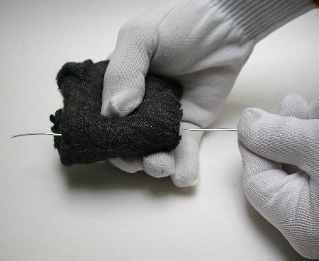
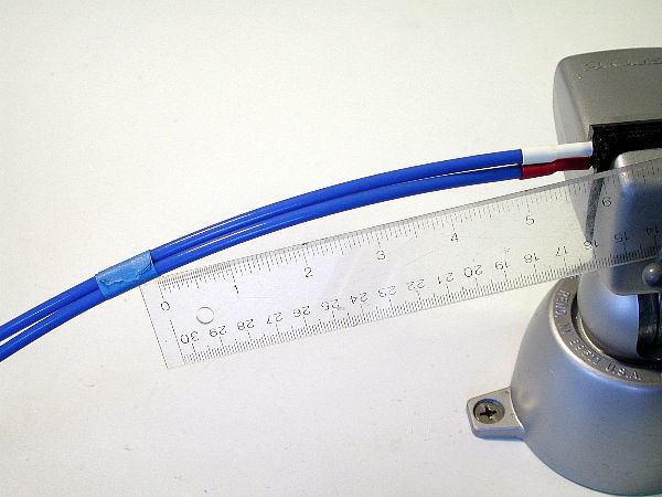
To polish, hold the wire with one hand and, to avoid kinking it, burnish it with the other hand, always drawing the steel wool over the wire in one direction, away from the anchor point. Alternatively, you can hold one end in a table-mounted vise or clamp and carefully draw the wire out toward you with one hand while using the steel wool to burnish it with the other, drawing the wire out and backing away from the clamp as you go.
PanaVise Models 301 and 381
I use a device called a PanaVise. The Model 301 (left) is designed to bolt directly to a workbench, but for the weekend DIYer, there's also the Model 381 (right) which features a suction base. If you use the 381, a good way to secure it to the table top is to dampen the base with a sponge and water before activating the suction clamp.
 Otherwise, I've found that the suction seal can break unexpectedly. The vise section of both units features a protective plastic cover on the clamps which prevents the wire from being damaged while being held in place.
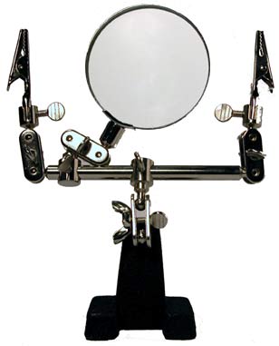
Another invaluable aid is the "helping hand" or "third hand" tool, shown above right. It's a set of articulated arms, with or without a magnifying glass, mounted on a weighted base and terminated with a set of alligator clips. While the PanaVise holds the RCA or XLR plug, the helping hand holds the wire.
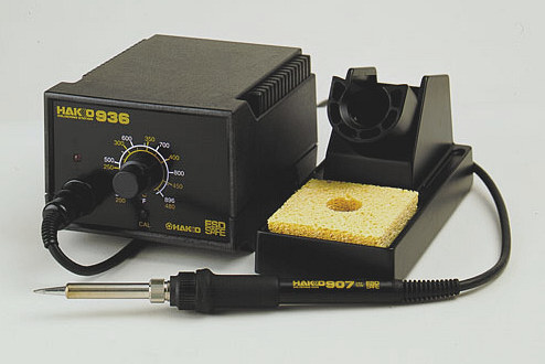
Next, a good soldering iron with a separate power supply, an adjustable thermostat, and interchangeable tips is an essential luxury. Once you've used one, you'll never want to go back to a single wand, single temperature iron. I personally like the Hakko 936ESD, which is safe for working on electrostatic sensitive devices, too. Weller makes a nice range of irons, as well.
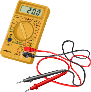 Finally, a continuity tester with an audible tone, is something you'll need to check that you're soldering the wires correctly from one plug to the other. These are often incorporated into multi-meters, ohm meters, and voltage meters. Make sure it has a long set of interchangeable test leads. An extra set of leads with small clips on the ends will make using the tester a lot easier as you probe the free ends of your wires.
Assembling the Interconnects
Next, cut the Teflon tubing to size. If you're fabricating interconnects, make sure the overall length of the tube is about 1/2" (12mm) shorter than the finished length, so that 1/4" (6.4mm) of bare wire is exposed at each end. For speaker cables, I usually make the jacket 3.5" shorter, overall, so that 1.75" of wire is left exposed at each end.
If the end of the wire is rough or has a slight burr, you may need to file the ends first to eliminate this. Also, check to see that the end of the insulating jacket is close to round. Often, when you cut the jacket, there's a tendency for the clippers to compress the body of the tubing into a oval. This not only makes insertion more difficult with similar size tubing and increases the possibility of creating a kink in the wire.
Cardas Silver Plated RCA Plugs
To terminate the interconnects, you'll need a good quality RCA plug. Cardas makes a very nice silver plated version (Model SLVR) which retails for about $20.00 per pair. Again, I prefer the WBT-0110Ag NextGen Locking RCA Plug which makes a much tighter fit, especially with it's matching socket. But with a suggested retail price of $360 for four pieces, they're very pricey and, for some, this calls into question the point of DIY economy. A new kid on the block is Eichmann Bullet Plug, also available in solid silver. A set of four in silver retails for about $185.00, but because of their plastic bodies, some users find them more difficult to install without causing damage. Recently, Eichmann introduced a version with an metal body (for about $20 more) that solves this problem.
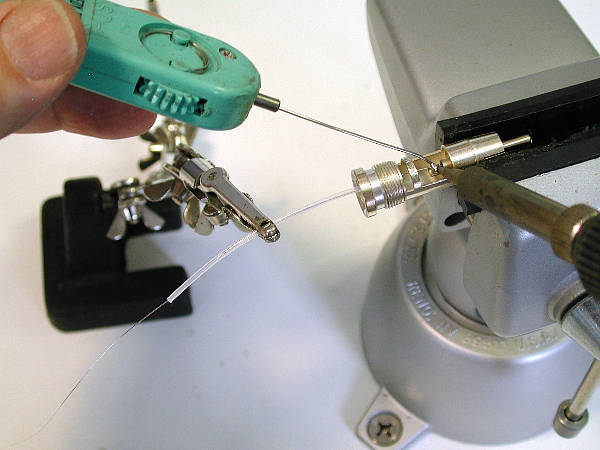
I used to thread the wire into the tubing prior to soldering, but now I solder first and thread later. To protect the bare wire from the clips, slip a short piece of scrap tubing over the wire. as shown below. Using the PanaVise to hold the body of the plug and the helping hand tool to hold the wire, leaves your hands free to solder.
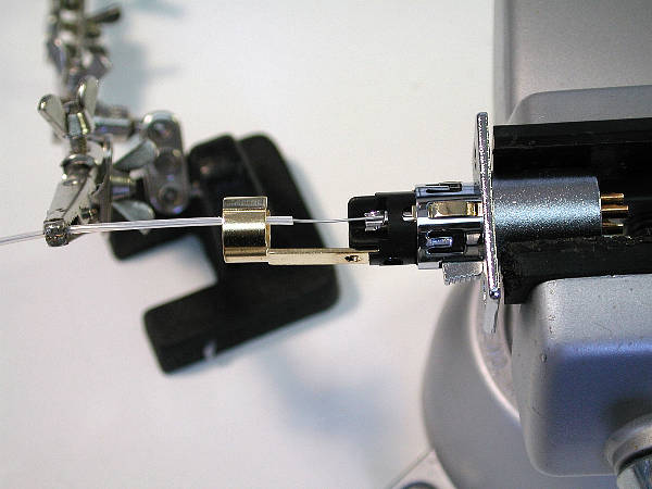
When you solder the wires, the positive conductor (+) always goes to the center pin and the negative (-) is attached to the outer ring or barrel. When soldering to an XLR connector (below), I mount an XLR panel connector of the opposite gender in the PanaVise and insert the line plug into it. If the insulating material in the XLR softens from the heat of the soldering iron, the pins may move and get out of alignment. Soldering the pins with the plug inside the panel connector prevents this.
After you've solder both conductors (three for the XLR), slip the tubing over the wires. Wearing a glove on your wire handling hand, hold the tubing in one hand while pushing 1 or 2 inches of wire in at a time with the other hand. If you're using similar size tubing, take your time! Small gauge wire is very easy to kink and kinks make smooth insertion difficult. Oversized tubing makes this step a breeze. If you happen to kink the wire (and you may at some point), just withdraw a few inches and smooth over that section with the steel wool. The straighter and smoother you can keep the line, the fewer problems you'll have threading it into the tube. It often helps to lay the tubing out straight, rather than try and feed it from the coil. If you're using oversized tubing, you may find that it's a tight fit to slip the ends into the barrel of the plug. Just take a medium width blade, needle nose pair of pilers and flatten the ends of the tubing. This makes insertion easier, especially with smaller barrel plugs. Ideally, the tubing will be snug enough at the opening of the barrel, that it acts as its own strain relief, preventing the wires from coming loose.
After you've slipped on the Teflon tubing, twist them together gently, three or four twists to a foot (300mm). This helps to cancel out stray magnetism and holds the tubing in place. When you reach the end, it often helps to wrap the tubes with a short piece of masking tape to hold them together while you prepare the other connector.
With the opposite connector in the PanaVise, turn on the continuity tester and clip one lead to the positive pin of the first connector. Touch the second lead to the free ends of the wires. The test tone indicates the positive conductor. Carefully slipping the jacketed wire into the second plug, solder the positive wire to the positive pin. Do the same with the negative lead and double check again with the tester. Remove the masking tape and you're done!
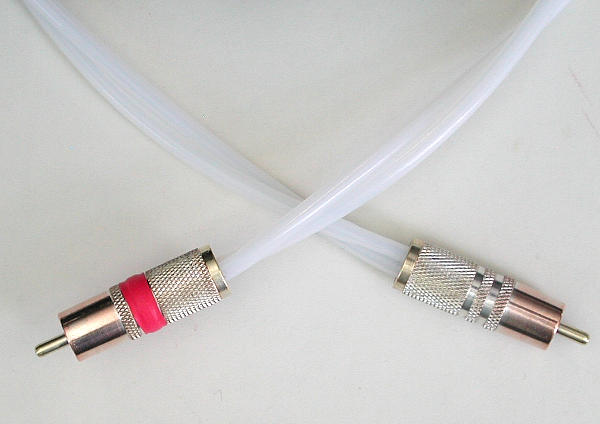
Some RCA plugs, like the Cardas model shown, do not come with color-coding. In that case, slip a piece of red heatshrink over the barrels of one cable to indicate the right interconnect. White heatshrink is optional for the other cable.
Assembling the Loudspeaker Cables
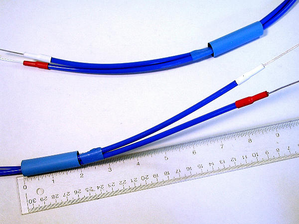
When fabricating the loudspeaker cables, leave 1-3/4" (44mm) of bare wire exposed at each end and overlap the wire and jacket with a 1" (25mm) long piece of 1/4" (6mm) diameter color-coded heatshrink tubing. If you can find it, adhesive-lined heatshrink helps to keep everything in place.
That now leaves 1-1/4" (32mm) of bare wire exposed—enough to make a J-hook or thread the end into the hole in the binding post. If there is a large difference in diameter between the tubing and the wire, it helps to slide a 1/2" (12mm) long piece of 1/8" (3.2mm) diameter heatshrink under the end of the 1/2" heatshrink that's in contact with the wire. It simply makes for a better fit.
Assembly is really straight forward. First, secure the two conductors at one end. In the photo, above, they are shown held in place in the Panavise, but you can use any clamp that does not damage or deform the wires. You can even have a friend hold them for you.
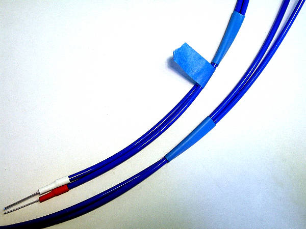
I like to leave six-inches (150mm) of parallel conductors at each end. Since you will probably have to bend them, this gives you enough length to slip the conductors onto the binding posts without stressing the wires. At the 6-inch mark from the end of the heatshrink, wrap the conductors with a piece masking tape to hold them together, as shown above.
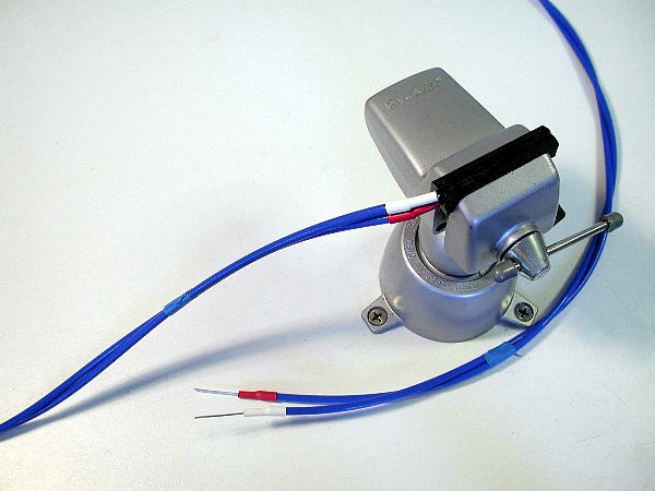
Next, give them a gentle twist, three or four twists for every foot (that's every 300mm). After you've twisted the entire length, leave another six inches of parallel wires free at the other end and wrap another piece of masking tape in place to hold them in place (shown above).
Next, slip a 2" (50mm) piece of 1/2"-3/4" (12mm-18mm) heatshrink over the wires, just after the tape at each end.
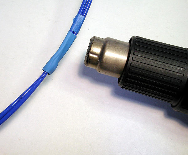
Apply heat to the heatshrink tubing with a heat gun set to 220°C-240°C or a hair dryer set to the hottest level.
After you've shrunk the heatshrink tubing down to size, remove the masking tape. If you wish, you can now add a set of spades. Depending on your preference, either solder a good quality spade or pin or just use the bare wire itself, which is what I often prefer. As Allen Wright says, "The best connector is no connector."
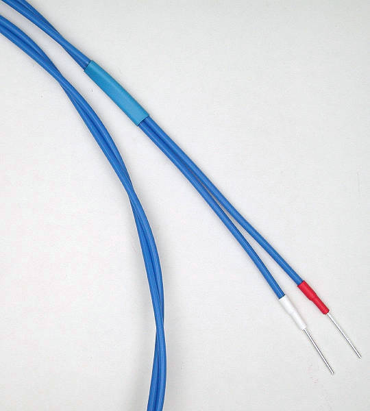
Finished speaker cables. Note the generous twists and color-coded heatshrink on the ends.
If you do go for spades, Michael Percy Audio offers a wide selection, as well as silver solder, at reasonable prices. My personal choice is the very expensive WBT-0660Ag or WBT-0680Ag Silver Signature Spade. For about $15 each, an economical alternative is the Goertz Audio Large Silver Spade. If you go the Goertz (formerly Alpha-Core) route, use lead-free WBT solder to attach them to your wires. The main reason to use spades instead of bare wire is durability. As mentioned, silver is relatively soft and if over tightened repeatedly, the bare wire can deform or even break-off.
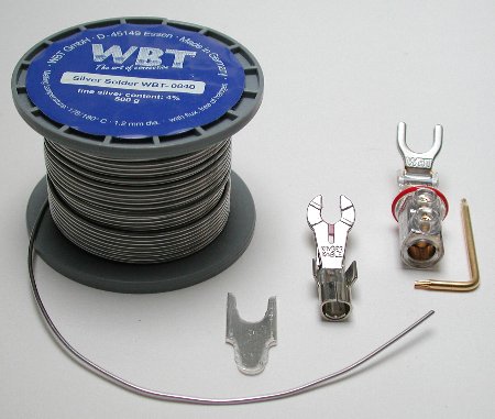
WBT Solder, Goertz Audio Large Silver Spade, Kimber Post Master, WBT-0680 + Torx Driver
If you're undecided about which termination (if any) is sonically superior, this paper [with emphasis on the conclusions added], written by former GE research engineer Bill Kenney and published in 1995 by the Boston Audio Society, finds that using no connector is best, followed by connectors whose metal content is identical to that of the wire, itself. In addition, his research (for a US Navy project) showed that given a choice, compression fittings are preferable to ones that are soldered on and, due to their relative lack of contact pressure, banana plugs are the worst termination of all. His observations about the sonic anomalies caused by the interface of dissimilar metals is why we use and recommend WBT silver binding posts and RCA sockets, as well as internal silver wire in the signal paths of all audio components, themselves. It's axiomatic that the more similar the conducting metal content is throughout the signal path, the better the end results will be.
Cables terminated with Goertz Audio Large Silver Spades
For a decorative touch, you can also add a protective cover of convoluted PVC and nylon mesh in the color of your choice. Seal the ends with a 4" pieces of heatshrink. There's a photo in the Introduction section of this article which illustrates this.
Oxidation
Some correspondents have expressed concern about the silver wire oxidizing inside the Teflon tubing. However, Prof. Alan J. Ardell of the Department of Materials Science and Engineering at UCLA writes, "silver doesn't oxidize at room temperature. The culprit is sulfur, which reacts with silver to form the tarnish that silver polish removes. Yes, there will be air between tubing of any kind and the wire, but to cause serious problems a fresh and ready supply of air is needed. Otherwise sulfidation will cease as soon as the local supply is used up. How much air flow is there likely to be between wire and tubing? Problems might arise from extra contact resistance of sulfurized silver in regions of contact with other conductors in the chain, but a thin layer of sulfide on the surface of silver wire won't cause any harm, at least to the conductivity of the wire."
In addition, Dr. Arthur Loesch, well known audio designer and Professor Emeritus of Atmospheric Dynamics at the State University of New York, maintains that fears of tarnish contaminating the sound are completely unfounded. As he puts it, "tarnish is still silver and it all sounds the same."
My personal experience is that after more than 10 years of service, there is no evidence of silver oxidation within the Teflon jacket, although it does appear on the exposed ends. Silver will oxidize, but the tarnish of silver is conductive—it's actually more conductive than polished silver—so oxidized silver still makes a good signal path. Don't confuse this effect with the surface oxidation that appears on copper, which is essentially a dead material with no conductive properties.
Enjoy The Music!
Voilà! You've now fabricated $5,000 cables for about $200 and never have to upgrade again...
At least not until you can afford to terminate those babies with NextGen Silvers.
| Don't have time for DIY? Please visit Tempo Electric, our sister site, where we fabricate custom interconnects, speaker cables, and power cords for only a modest increase above the cost of materials. We also sell a full range of pure silver wire with Teflon jacketing by the foot or by the meter for DIY projects. |
Return to: Good Sound For $1,000?
 |
 |
 |
 |
 |
Main Page |
|---|